Steelmaking can also use ceramic valves
Author—FUVALVE ENGINEER
Steelmaking dedusting
At present there are many kinds of dust removal process, the form of steelmaking dust removal system is also diverse, due to the form of different, dust removal system facilities and composition is not the same, but the basic process flow is unchanged, including flue gas collection part, flue gas cooling part, waste heat recovery part, flue gas purification part, gas recycling and gas discharging part, sewage treatment part, and dust recovery part.
Dedusting process
There are three methods to separate the gas from the dust in the flue gas, namely wet, dry and semi-dry.
Wet de-dusting
It is to use water or water vapor to absorb the dust in the flue gas into the water first, so that the dust and gas separation, and then in a variety of dewatering methods will be separated from the dust and water, the water can be recycled, the dust can also be recycled. Commonly used process equipment include ventilator, spray tower, scrubber tower, dewaterer, screen mist eliminator and so on.
Dry dust removal
Coarse dust removal is to use water vapor to remove dust, but after the removal of dust all the water vapor evaporates, or the use of gravity, inertia dust removal, the separated dust is dry state; and fine dust removal is the use of bag filtration, electrostatic and other ways to separate the dust in the flue gas from the gas, the whole system separates the dust is dry.
Semi-dry de-dusting
It is a special kind of dust removal equipment, coarse dust removal with dry method, fine dust removal with wet method, the separated dust has both dry dust and mud, also known as dry and wet method.
At present, there are many kinds of dust removal process, the form of dust removal system in the steel mill is also diverse, due to the different forms, dust removal system facilities and composition is not the same, but the basic process flow is unchanged, including flue gas collection part, flue gas cooling part, the waste heat recovery part, flue gas purification part, gas recycling and gas discharging part, sewage treatment part, and dust recovery part.
Nature of flue gas
The gas formed by metallurgical or combustion processes contains a certain amount of moisture and other components, commonly known as flue gas.
Flue gas properties can be discussed in the following aspects:
Large temperature fluctuations
The flue gas temperature at the exhaust pipe entering the furnace is generally 800~1000℃, the flue gas temperature out of the water-cooled flue is designed to be 450~600℃, the flue gas temperature out of the forced blowing cooler (or natural air cooler) is controlled to be 250~400℃, and the outlet temperature must be controlled to be 200~280℃ when using the evaporative cooling tower emergency cooling device.
Complex composition
Due to the electric furnace steelmaking process and the different raw materials used, resulting in changes in the composition of the soot, in addition to the main iron oxides, there are some other metal oxides, carbon particles and so on. In the bag filter, if these dusts meet the humid gas condensation, it may lead to the blockage of the filter media, not easy to clear the dust, and the resistance of the equipment is larger.
Fine dust particles
The dust particles produced by high temperature smelting process are fine, and most of its average particle size is less than 10μm, which is also an important reason for the increase of resistance of some equipment after a period of use.
Dust concentration varies greatly
The dust content of the flue gas is one of the important parameters for the selection of bag-type dust collector and the consideration of dust collection and treatment equipment. Generally, the dust concentration (standard state) of the smoke discharged outside the furnace cover is 1.30~1.50g/m3, and the dust concentration in the smoke discharged inside the furnace is 15~20 g/m3, which is related to the quality of raw materials, smelting process, and design of the dust removal system of the steelmaking. When the quality of raw materials is poor, the concentration of soot produced by electric furnace steelmaking is large.
Dew point
When the temperature of flue gas decreases continuously to a certain value, part of the water vapor in the flue gas will condense into water droplets, i.e., dew phenomenon occurs, and the temperature at the time of dew becomes the dew point. The dew point formed in the flue gas due to the acidic gas is called acid dew point. The generation of acid dew point not only creates trouble to the dust removal effect, but also accelerates the corrosion of equipment and materials.
Smoke exhaust method
Smoke exhaust can be mainly divided into two ways of smoke exhaust inside the furnace and outside the furnace, usually called primary smoke exhaust and secondary smoke exhaust.
Furnace exhaust
Furnace exhaust mainly captures the smelting of high-temperature flue gas discharged, commonly used in the furnace exhaust: direct furnace exhaust, the level of open-type furnace exhaust and bend open-type furnace exhaust and other forms.
Furnace exhaust
The primary flue gas during melting is captured by the furnace exhaust device, but it can not capture the secondary flue gas when charging, discharging steel, and mixing molten iron, etc. The secondary flue gas is sudden and discharged in an unorganized manner, so it can only rely on the exhaust device outside of the furnace to capture, and the commonly used exhaust devices outside of the furnace include the roof hood exhaust and the airtight hood exhaust and other forms.
Exhaust smoke from iron dephosphorization station
The blast furnace molten iron from the molten iron pouring station after mixing and flushing desiliconization, in the molten iron dephosphorization station for molten iron dephosphorization blowing and slagging, blowing and slagging on the top of the respectively set up a fixed extractor hood, the temperature is usually in the range of 250 ~ 550 ℃.
Ash Discharge Device
The gas purified by the dust removal system is discharged from the chimney, while the dust collected by the dust removal equipment is stored and transported by the ash conveying and discharging device, which is usually divided into mechanical conveying and pneumatic conveying. The dust conveying and discharging device mainly consists of: dust conveying device, dust discharging device and dust storage bin and other equipment.
Pneumatic conveying
Pneumatic conveying is a kind of conveying device to convey dust with the gas flowing in the pipeline as the carrier. Commonly used dust pneumatic conveying device has two kinds of low-pressure inhalation type and low-pressure pressure sending type.
Low-pressure inhalation type pneumatic conveying
The high pressure fan is arranged behind the separator of the conveying system, the design requires the system to be tight without air leakage, and at the same time requires that the humidity of the dust gas to be conveyed should not be too large to ensure that the system is not blocked.
Low Pressure Pneumatic Conveying
The conveying system is running under positive pressure, in order to prevent the pipeline leakage caused by the secondary pollution of dust, the same requirements of the system is tight without air leakage, and requires sufficient origin and gas supply pressure.
Pneumatic conveying equipment and main fittings
It consists of feeding device, conveying device, separator, pumping and supplying equipment and ash unloading valve class.
Feeding device
The feeding device is set under the dust hopper of the dust removal equipment and the front end of the conveying pipeline, and the dust to be conveyed is continuously and evenly fed into the conveying pipeline.
Conveying pipe
Conveying pipe includes straight pipe and bend pipe, according to the nature of dust for the design of the system and the selection of pipe materials. Bend pipe is the most wearable and dust-accumulating pipe in pneumatic conveying device.
Separator
The purpose of separator in the conveying system is to separate the gas and dust, which also belongs to the category of dust collector.
Pumping and supplying equipment
The conveying power of the pneumatic conveying system comes from the pumping and supplying equipment, low-pressure inhalation type and low-pressure pressure feeding type generally adopts high-pressure centrifugal machine or Roots blower.
Ash unloading valve
For inhalation system, in order to ensure the tightness of the unloading port, the ash discharge valve is set in the separator;
For the pressure-fed system, in order to make the separator unloading dust is not generated by the secondary dust, in the unloading port out of the set of ash unloading valve.
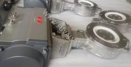
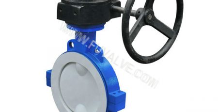
Application of ceramic valve
The system of the ash conveyor system in the ash conveyor valve due to frequent action, often under pressure to open and close, to withstand the rapid scouring of dust, working conditions are exceptionally harsh, the position of the valve will often be used to close in place, closed not tight, the valve plate valve valve valve wear and tear fast, the use of short life and other issues.
For such dust removal and ash transportation working conditions, the advantages of ceramic valves are:
Seal tight and reliable, in the case of slight wear on the sealing surface can still be closed tightly, to prevent further aggravation of wear;
The accumulation of dust in the valve body has little effect on the sealing of the valve;
The sealing material is sufficiently hard and resistant to wear;
The flow capacity of the valve is good, and the efficiency of ash transfer should be high.
Picture
Sinter desulfurization
In China, flue gas desulfurization (FGD) in the iron and steel industry has become the focus of SO2 emission control after flue gas desulfurization of thermal power generating units.
According to whether water is added to the desulfurization process and the dry and wet form of the desulfurization product, it can be divided into three categories of desulfurization processes: wet, semi-dry and dry, and the main processes that have been applied are limestone-gypsum method, ammonia-ammonium sulfate method, circulating fluidized bed method, rotary spray drying method, magnesium oxide method, double alkali method and more than ten kinds.
Sinter flue gas desulfurization
Sintering flue gas is the dusty exhaust gas produced during the high temperature sintering process after the mixture is ignited.
The concentration of SO2 in the flue gas produced during the production of sintering machine varies greatly, and the concentration of SO2 in its head and tail flue gas is low and high in the middle. Iron oxides in the sintered material will act as a catalyst to catalyze the oxidation of part of the SO2 to SO3.
Part of the organic sulfur in the ore powder is transferred to the gas phase as monomer sulfur and oxidized, due to the existence of temperature inhomogeneity in the sintering process, the exhaust flue gas also contains H2S and CaS.
In addition, the chlorides in the mixture will also generate volatile chlorides into the flue gas during the sintering process. The characteristics of the sintered flue gas determine the characteristics and difficulties of the desulfurization of the sintered flue gas, and it is not possible to directly copy the desulfurization technology of the power plant.
Desulfurization process
Iron and steel production SO2 emissions mainly come from sintering, coking and power production:
Sulfur in the raw ore and fuel coal of the sintering process is oxidized into SO2, which exists in the sintering flue gas;
Sulfur in coking coal in the coking process generates H2S, which exists in the coke oven gas, which generates SO2 after combustion;
Sulfur in power production fuel coal combustion directly generates SO2.
The SO2 emitted from the sintering process accounts for more than 60% of the total emissions from iron and steel production, and is the main source of SO2 emissions in the iron and steel production process.
Picture
Limestone-Gypsum Method
It is the most widely used and mature wet desulfurization technology.
Limestone-gypsum method is a method that uses slurry of lime or limestone in the scrubber tower to absorb S02 in the flue gas and by-produce gypsum. Since the absorbing slurry is recycled, the utilization rate of desulfurization absorbent is high.
This desulfurization system mainly includes: absorbent preparation system, flue gas system, sulfur dioxide absorption system, gypsum dehydration and storage system.
The process principle is to absorb S02 in the flue gas with lime or limestone slurry, which is divided into two stages: absorption and oxidation. First absorption generates CaS03, and then CaS03 is oxidized into CaS04, i.e. gypsum.
Its technology is mature; the system is stable and reliable; it is a gas-liquid reaction, with fast reaction speed; high efficiency of desulfurization; low price of desulfurization agent; and wide adaptability.
Ammonia-Ammonium Sulfate Method (Ammonia Method)
Ammonia desulfurization technology is a process that uses ammonia (NH3) as an absorbent to remove S02 from the flue gas. Because of the high price of ammonia, the ammonia method is necessarily a recovery method.
The ammonia desulfurization system mainly includes: ammonia preparation and storage system, flue gas system, sulfur dioxide absorption system, ammonium sulfur separation and storage and transportation system.
Its working principle is that the absorbing liquid enters the heat exchanger for cooling, and then through the circulating pump from the absorption section of the tower into the desulfurization tower, the flue gas enters the desulfurization tower from the lower part, and the liquid ammonia reaction with the absorbing liquid sprayed out, and then through the demister to remove the fog into the chimney after the exhaust. The absorbing liquid is recycled to a certain concentration, and after forced oxidation, ammonium sulfate is produced as a by-product of desulfurization.
It has the advantages of high desulfurization efficiency and good prospect of by-product utilization.
Circulating Fluidized Bed Method (CFB-FGD)
Circulating Fluidized Bed Flue Gas Desulphurization (CFB-FGD) generally adopts dry lime powder (CaO) or lime powder (Ca(OH)2) as the absorber, and lime powder is added into the flue gas in a certain proportion, so that the lime powder is in the fluidized state in the flue gas, and reacts with SO2 to form calcium sulfite.
A typical CFB-FGD system for sintered flue gas desulphurization consists of absorbent supply system, desulphurization tower, material recirculation, process water system, post desulphurization dust collector and instrumentation control system.
Spray drying method (SDA)
Spray drying flue gas desulphurization technology is sintered flue gas after pre-dusting into the desulphurization tower, the flue gas and the atomized lime slurry droplets in the desulphurization tower to fully contact the reaction, the reaction product is dried, in the desulphurization tower mainly complete the chemical reaction, to achieve the purpose of absorbing SO2.
By absorbing SO2 and drying the flue gas containing powder in the desulfurization tower progress bag filter for gas-solid separation, to achieve the collection of desulfurization ash and the export of dust concentration to meet the emission standards. Activated carbon is added to the inlet flue of the dust collector to further remove other harmful substances, and the flue gas treated by the dust collector is discharged into the atmosphere by the chimney.
The SDA system can also use part of the desulfurization products to recycle slurry to improve the utilization rate of the desulfurizer.
Magnesium oxide method
Magnesium oxide method of desulfurization is the magnesium oxide through the slurry preparation system made of magnesium hydroxide supersaturated liquid, in the desulfurization absorption tower and sintering flue gas full contact, and sintering flue gas in the SO2 reaction to generate magnesium sulfite, magnesium sulfite slurry discharged from the absorption tower can be dewatered and reprocessed to produce sulfuric acid.
The system mainly includes 3 parts: solution preparation and delivery, flue gas cooling, desulfurization and liquid water treatment.
Bi-alkali method
Dual-alkali desulfurization process is the sintering machine flue gas purified by dust collector, introduced into the desulfurization tower by the induced draft fan, SO2-containing flue gas tangentially into the tower, and spiral upward under the guiding effect of cyclone plate; flue gas in the cyclone and desulfurization liquid counter-current convection contact with the desulfurization liquid on the cyclone plate atomization of desulfurization liquid on the cyclone plate, the formation of a good atomized absorption area, flue gas and desulfurization liquid alkaline desulfurization agent in the atomization zone in the full contact and reaction to complete the The flue gas and the alkaline desulfurization agent in the desulfurization liquid fully contact and react in the atomized area to complete the desulfurization and absorption process.
After desulfurization, the flue gas passes through the mist elimination plate arranged in the upper part of the tower, using the rotating effect of the flue gas itself and the guiding effect of the cyclone mist elimination plate to produce a strong centrifugal force, the liquid droplets in the flue gas are thrown to the wall of the tower, so as to achieve high efficiency mist elimination, the mist elimination efficiency of up to 99% or more, and the desulfurized flue gas is directly discharged into the top chimney of the tower.
Absorbent commonly used alkali are soda ash (Na2CO3), caustic soda (NaOH) and so on. Its operation process is divided into three stages: absorption, regeneration and solid-liquid separation.
The system mainly consists of SO2 absorption system, desulfurizer preparation system, desulfurization by-product treatment system, desulfurization and dust removal water supply system and electrical control system.
NID Method
NID technology utilizes lime (CaO) or slaked lime (Ca(OH)2) as the desulfurization agent to absorb SO2 and other acid gases in the flue gas.
The flue gas at about 130°C is led from the exit flue of the sintering main extractor fan into the reactor, where physical changes and chemical reactions are rapidly completed, and SO2 in the flue gas reacts with the desulfurization agent to form CaSO3 and CaSO4.
After the reaction, the flue gas carries a large number of dried solid particles into the dust collector, and separated from the flue gas, through the ash recycling system, supplementing the desulfurization agent, humidifying and mixing it again, and sending it to the reactor.
This cycle for many times, to achieve the purpose of efficient desulfurization and improve the utilization rate of absorbent. After desulfurization and dust removal, the clean flue gas is above 20℃ in the dew point temperature of water vapor, without heating, and is discharged into the chimney through the pressurized fan.
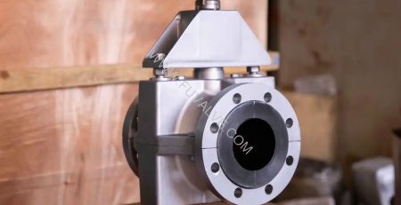
Ceramic Valve used to the applications
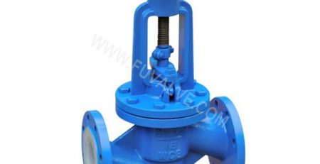
Flue gas discharge
Due to the complexity of the corrosive components of the flue gas medium, can be found inside the sealing surface in contact with the flue gas corrosion is serious, dusty flue gas is easy to make the valve dust scale, thickening of the dust scale will impede the valve movement, to remove these dust scale operation is extremely inconvenient, time-consuming and laborious;
If the water vapor in the gas condensation occurs, the corrosiveness of the resolved gas will be greatly enhanced. Especially in the role of HCl, etc., it is easier to induce intergranular corrosion of austenitic stainless steel, accelerating the corrosion failure of the piping system. Pipeline if the catalyst dust bonding occurs, bonding the formation of the block porosity is large, will be adsorbed in the resolution of corrosive components of the gas, resulting in bonding at the pipeline components surface corrosive medium to enhance the acceleration of bonding at the corrosion of the metal surface. In addition, the coexistence of SO2, SO3 and NH3 also increases the risk of catalyst dust bonding and promoting metal corrosion.
Ordinary wear-resistant materials are difficult to meet the needs of corrosion resistance at the same time, you can consider ceramic materials that can withstand wear, corrosion and high-temperature oxidation at the same time. It can effectively avoid the problem of poor sealing of the valve due to corrosion and abrasion, and greatly extend the service life of the valve.
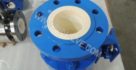
Lime / gypsum slurry transportation
The abrasion of slurry is mainly due to the impact and damage of solid particles (especially silicate) in the slurry on the abraded materials. Flue gas desulfurization slurry media mainly consists of limestone (CaCO3) particles (containing a small amount of SiO2) or gypsum (CaSO4-2H2O) particles and water. At higher flow rates, these particles can cause severe abrasion or erosion to the inner wall of the pipe.
At the same time, the slurry is weakly acidic, and also mixed with some chloride ions, etc., these substances will have a chemical reaction with the metal pipe wall and make the steel pipe corrosion, until rotten through, affecting the service life of the desulfurization device.
Cl- easier than oxygen adsorption on the metal surface, and the oxygen crowded out, so that the passivation of the metal state has been partially destroyed and the occurrence of pore corrosion, some stainless steel materials are also difficult to avoid. Slurry corrosion of metal pipes in the form of: pitting, crevice corrosion, stress corrosion, fatigue corrosion, galvanic corrosion and so on.
In addition, the slurry pipe for two-phase flow. Two phase flow is characterized by the flow rate must be controlled within the appropriate range. High flow rate is prone to wear and tear and greatly increase the resistance of the pipeline, while the flow rate is low will produce deposits, narrowing the circulation surface of the pipeline, until blocked.
-400x231.jpg)