Bei der Stahlherstellung können auch Keramikventile zum Einsatz kommen
Autor—FUVALVE-INGENIEUR
Entstaubung der Stahlerzeugung
Gegenwärtig gibt es viele Arten von Staubentfernungsverfahren, Auch die Form des Entstaubungssystems für die Stahlherstellung ist vielfältig, aufgrund der Form unterschiedlich, Die Ausstattung und Zusammensetzung des Staubentfernungssystems ist nicht gleich, Der grundlegende Prozessablauf bleibt jedoch unverändert, inklusive Rauchgassammelteil, Rauchgaskühlungsteil, Teil zur Abwärmerückgewinnung, Rauchgasreinigungsteil, Gasrecycling- und Gasableitungsteil, Teil der Abwasserbehandlung, und Staubrückgewinnungsteil.
Entstaubungsprozess
Es gibt drei Methoden, um das Gas vom Staub im Rauchgas zu trennen, nämlich nass, trocken und halbtrocken.
Entstaubungsgesetz
Dabei wird zunächst Wasser oder Wasserdampf verwendet, um den Staub im Rauchgas ins Wasser zu absorbieren, damit die Staub- und Gastrennung erfolgt, und dann in verschiedenen Entwässerungsverfahren vom Staub und Wasser getrennt werden, Das Wasser kann recycelt werden, Der Staub kann auch recycelt werden. Zu den häufig verwendeten Prozessgeräten gehören Ventilatoren, Sprühturm, Wäscherturm, Entwässerer, Siebnebelabscheider und so weiter.
Trockene Staubentfernung
Bei der Grobstaubentfernung wird Wasserdampf zur Staubentfernung eingesetzt, aber nach der Staubentfernung verdunstet der gesamte Wasserdampf, oder die Nutzung der Schwerkraft, Staubentfernung durch Trägheit, Der abgeschiedene Staub liegt im trockenen Zustand vor; Bei der Feinstaubentfernung kommt die Beutelfiltration zum Einsatz, elektrostatische und andere Methoden, um den Staub im Rauchgas vom Gas zu trennen, Das gesamte System trennt den Staub trocken.
Halbtrockene Entstaubung
Es handelt sich um eine besondere Art von Staubentfernungsgerät, Grobstaubentfernung im Trockenverfahren, Feinstaubentfernung im Nassverfahren, Der abgeschiedene Staub besteht sowohl aus trockenem Staub als auch aus Schlamm, auch als Trocken- und Nassmethode bekannt.
Derzeit, Es gibt viele Arten von Staubentfernungsverfahren, Auch die Form der Entstaubungsanlage im Stahlwerk ist vielfältig, aufgrund der unterschiedlichen Formen, Die Ausstattung und Zusammensetzung des Staubentfernungssystems ist nicht gleich, Der grundlegende Prozessablauf bleibt jedoch unverändert, inklusive Rauchgassammelteil, Rauchgaskühlungsteil, der Teil der Abwärmerückgewinnung, Rauchgasreinigungsteil, Gasrecycling- und Gasableitungsteil, Teil der Abwasserbehandlung, und Staubrückgewinnungsteil.
Art des Rauchgases
Das durch metallurgische oder Verbrennungsprozesse entstehende Gas enthält eine gewisse Menge an Feuchtigkeit und anderen Bestandteilen, allgemein als Rauchgas bekannt.
Die Eigenschaften von Rauchgasen können unter folgenden Gesichtspunkten diskutiert werden:
Große Temperaturschwankungen
Die Rauchgastemperatur am Abgasrohr, das in den Ofen eintritt, beträgt im Allgemeinen 800 bis 1000 °C, Die Rauchgastemperatur aus dem wassergekühlten Rauchabzug ist auf 450 bis 600 °C ausgelegt, die Rauchgastemperatur aus dem Zwangskühler (oder natürlicher Luftkühler) wird auf 250~400℃ geregelt, und die Auslasstemperatur muss auf 200 bis 280 °C geregelt werden, wenn das Notkühlgerät des Verdunstungskühlturms verwendet wird.
Komplexe Komposition
Aufgrund des Elektroofen-Stahlherstellungsprozesses und der unterschiedlichen verwendeten Rohstoffe, Dies führt zu Veränderungen in der Zusammensetzung des Rußes, zusätzlich zu den wichtigsten Eisenoxiden, Es gibt einige andere Metalloxide, Kohlenstoffpartikel und so weiter. Im Beutelfilter, Treffen diese Stäube auf das feuchte Gas, kommt es zur Kondensation, Dies kann zur Verstopfung des Filtermediums führen, Es ist nicht einfach, den Staub zu entfernen, und der Widerstand der Ausrüstung ist größer.
Feine Staubpartikel
Die beim Hochtemperatur-Schmelzprozess entstehenden Staubpartikel sind fein, und der größte Teil seiner durchschnittlichen Partikelgröße beträgt weniger als 10 μm, Dies ist auch ein wichtiger Grund für die zunehmende Widerstandsfähigkeit einiger Geräte nach einer gewissen Nutzungsdauer.
Die Staubkonzentration variiert stark
Der Staubgehalt des Rauchgases ist einer der wichtigen Parameter für die Auswahl eines Beutelstaubabscheiders und die Berücksichtigung der Staubabsaug- und -behandlungsausrüstung. Allgemein, die Staubkonzentration (Standardzustand) Der außerhalb der Ofenabdeckung abgegebene Rauch beträgt 1,30 bis 1,50 g/m3, und die Staubkonzentration im Rauch, der in den Ofen austritt, beträgt 15–20 g/m3, was mit der Qualität der Rohstoffe zusammenhängt, Schmelzprozess, und Design des Entstaubungssystems der Stahlerzeugung. Wenn die Qualität der Rohstoffe schlecht ist, Die Rußkonzentration, die bei der Stahlherstellung im Elektroofen entsteht, ist hoch.
Taupunkt
Wenn die Temperatur des Rauchgases kontinuierlich auf einen bestimmten Wert absinkt, Ein Teil des Wasserdampfes im Rauchgas kondensiert zu Wassertröpfchen, d.h., Es kommt zum Tauphänomen, und die Temperatur zum Zeitpunkt des Taus wird zum Taupunkt. Der durch das Sauergas im Rauchgas entstehende Taupunkt wird Säuretaupunkt genannt. Die Bildung eines Säuretaupunkts beeinträchtigt nicht nur die Staubentfernungswirkung, but also accelerates the corrosion of equipment and materials.
Smoke exhaust method
Smoke exhaust can be mainly divided into two ways of smoke exhaust inside the furnace and outside the furnace, usually called primary smoke exhaust and secondary smoke exhaust.
Furnace exhaust
Furnace exhaust mainly captures the smelting of high-temperature flue gas discharged, commonly used in the furnace exhaust: direct furnace exhaust, the level of open-type furnace exhaust and bend open-type furnace exhaust and other forms.
Furnace exhaust
The primary flue gas during melting is captured by the furnace exhaust device, but it can not capture the secondary flue gas when charging, discharging steel, and mixing molten iron, etc. The secondary flue gas is sudden and discharged in an unorganized manner, Es kann also nur auf die Absaugvorrichtung außerhalb des Ofens zurückgegriffen werden, Zu den üblicherweise verwendeten Absaugvorrichtungen außerhalb des Ofens gehören die Dachhaubenabluft und die luftdichte Haubenabluft sowie andere Formen.
Abgasrauch aus der Eisenentphosphorungsstation
Das geschmolzene Eisen des Hochofens aus der Gussstation für geschmolzenes Eisen nach dem Mischen und Spülen der Entsilikonisierung, in der Entphosphorungsstation für geschmolzenes Eisen zum Blasen und Verschlacken der Entphosphorung von geschmolzenem Eisen, Einblasen und Verschlacken auf der Oberseite der jeweils fest installierten Dunstabzugshaube, Die Temperatur liegt normalerweise im Bereich von 250 ~ 550 ℃.
Ascheaustragsgerät
Das durch das Entstaubungssystem gereinigte Gas wird aus dem Schornstein abgeleitet, während der von der Entstaubungsanlage gesammelte Staub von der Ascheförder- und -austragsvorrichtung gespeichert und transportiert wird, die üblicherweise in mechanische Förderung und pneumatische Förderung unterteilt wird. Die Staubförder- und -austragsvorrichtung besteht im Wesentlichen aus: Staubfördergerät, Staubaustragsvorrichtung, Staublagerbehälter und andere Geräte.
Pneumatische Förderung
Bei der pneumatischen Förderung handelt es sich um eine Art Fördergerät zur Staubförderung, wobei das in der Rohrleitung strömende Gas als Träger dient. Häufig verwendete pneumatische Staubfördergeräte verfügen über zwei Arten von Niederdruck-Inhalationstypen und Niederdruck-Drucksendetypen.
Pneumatische Niederdruck-Inhalationsförderung
Der Hochdruckventilator ist hinter dem Abscheider der Förderanlage angeordnet, Die Konstruktion erfordert, dass das System dicht ist und keine Luftlecks aufweist, und erfordert gleichzeitig, dass die Feuchtigkeit des zu fördernden Staubgases nicht zu groß sein darf, um sicherzustellen, dass das System nicht blockiert wird.
Pneumatische Niederdruckförderung
Das Fördersystem läuft unter Überdruck, um zu verhindern, dass die Rohrleitung durch sekundäre Staubverschmutzung ausläuft, Die gleichen Anforderungen an das System sind dicht, ohne dass Luft austritt, und erfordert einen ausreichenden Ursprungs- und Gasversorgungsdruck.
Pneumatische Fördergeräte und Hauptarmaturen
Es besteht aus einem Fütterungsgerät, Fördergerät, Separator, Pump- und Versorgungsausrüstung und Klasse der Ascheentleerungsventile.
Fütterungsgerät
Die Zuführvorrichtung wird unter dem Staubtrichter der Entstaubungsanlage und dem vorderen Ende der Förderleitung angebracht, and the dust to be conveyed is continuously and evenly fed into the conveying pipeline.
Conveying pipe
Conveying pipe includes straight pipe and bend pipe, according to the nature of dust for the design of the system and the selection of pipe materials. Bend pipe is the most wearable and dust-accumulating pipe in pneumatic conveying device.
Separator
The purpose of separator in the conveying system is to separate the gas and dust, which also belongs to the category of dust collector.
Pumping and supplying equipment
The conveying power of the pneumatic conveying system comes from the pumping and supplying equipment, low-pressure inhalation type and low-pressure pressure feeding type generally adopts high-pressure centrifugal machine or Roots blower.
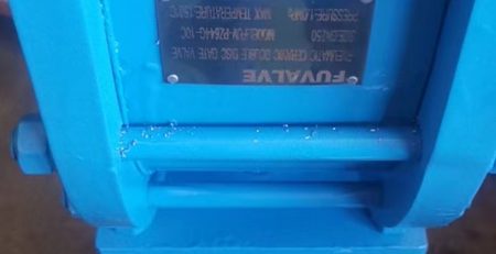
Ash unloading valve
For inhalation system, in order to ensure the tightness of the unloading port, the ash discharge valve is set in the separator;
For the pressure-fed system, in order to make the separator unloading dust is not generated by the secondary dust, in the unloading port out of the set of ash unloading valve.
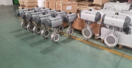
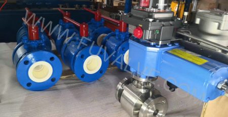
Application of ceramic valve
The system of the ash conveyor system in the ash conveyor valve due to frequent action, often under pressure to open and close, to withstand the rapid scouring of dust, working conditions are exceptionally harsh, the position of the valve will often be used to close in place, closed not tight, the valve plate valve valve valve wear and tear fast, the use of short life and other issues.
For such dust removal and ash transportation working conditions, the advantages of ceramic valves are:
Dicht und zuverlässig abdichten, bei leichtem Verschleiß der Dichtfläche noch dicht verschließbar, um eine weitere Verschärfung des Verschleißes zu verhindern;
Die Ansammlung von Staub im Ventilgehäuse hat kaum Auswirkungen auf die Dichtigkeit des Ventils;
Das Dichtungsmaterial ist ausreichend hart und verschleißfest;
Die Durchflusskapazität des Ventils ist gut, und die Effizienz der Ascheübertragung sollte hoch sein.
Bild
Sinterentschwefelung
In China, Rauchgasentschwefelung (REA) in der Eisen- und Stahlindustrie ist nach der Rauchgasentschwefelung von Wärmekraftwerken zum Schwerpunkt der SO2-Emissionskontrolle geworden.
Abhängig davon, ob dem Entschwefelungsprozess Wasser zugesetzt wird und in welcher trockenen und nassen Form das Entschwefelungsprodukt vorliegt, Es kann in drei Kategorien von Entschwefelungsprozessen unterteilt werden: nass, halbtrocken und trocken, Die wichtigsten angewandten Verfahren sind das Kalkstein-Gips-Verfahren, Ammoniak-Ammoniumsulfat-Methode, Verfahren mit zirkulierender Wirbelschicht, Rotationssprühtrocknungsverfahren, Magnesiumoxid-Methode, Doppelalkalimethode und mehr als zehn Arten.
Sinter-Rauchgasentschwefelung
Sinterrauchgas ist das staubförmige Abgas, das beim Hochtemperatur-Sinterprozess nach dem Zünden der Mischung entsteht.
Die SO2-Konzentration im Rauchgas, das bei der Herstellung von Sintermaschinen entsteht, schwankt stark, und die Konzentration von SO2 in seinem Kopf- und Schwanzrauchgas ist niedrig und in der Mitte hoch. Eisenoxide im Sintermaterial wirken als Katalysator und katalysieren die Oxidation eines Teils des SO2 zu SO3.
Ein Teil des organischen Schwefels im Erzpulver wird als Monomerschwefel in die Gasphase überführt und oxidiert, aufgrund der Temperaturinhomogenität im Sinterprozess, Das Abgas enthält außerdem H2S und CaS.
Und dazu, Die Chloride in der Mischung erzeugen während des Sinterprozesses auch flüchtige Chloride im Rauchgas. Die Eigenschaften des gesinterten Rauchgases bestimmen die Eigenschaften und Schwierigkeiten der Entschwefelung des gesinterten Rauchgases, und es ist nicht möglich, die Entschwefelungstechnologie des Kraftwerks direkt zu kopieren.
Entschwefelungsprozess
SO2-Emissionen entstehen bei der Eisen- und Stahlproduktion hauptsächlich beim Sintern, Verkokung und Stromerzeugung:
Schwefel im Roherz und in der Brennkohle des Sinterprozesses wird zu SO2 oxidiert, welches im Sinterrauchgas vorhanden ist;
Schwefel in Kokskohle erzeugt beim Verkokungsprozess H2S, welches im Koksofengas vorhanden ist, welches nach der Verbrennung SO2 erzeugt;
Bei der Verbrennung von Kohle in der Energieerzeugung entsteht durch Schwefel direkt SO2.
Das beim Sinterprozess freigesetzte SO2 macht mehr als aus 60% der Gesamtemissionen der Eisen- und Stahlproduktion, und ist die Hauptquelle von SO2-Emissionen im Eisen- und Stahlproduktionsprozess.
Bild
Kalkstein-Gips-Methode
Es handelt sich um die am weitesten verbreitete und ausgereifteste Nassentschwefelungstechnologie.
Bei der Kalkstein-Gips-Methode handelt es sich um eine Methode, bei der Kalk- oder Kalksteinschlamm im Wäscherturm verwendet wird, um S02 im Rauchgas zu absorbieren und Gips als Nebenprodukt zu erzeugen. Da die absorbierende Aufschlämmung recycelt wird, Die Ausnutzungsrate des Entschwefelungsabsorptionsmittels ist hoch.
Dieses Entschwefelungssystem umfasst hauptsächlich: Absorbierendes Vorbereitungssystem, Rauchgasanlage, Schwefeldioxid-Absorptionssystem, Gipsentwässerungs- und -speichersystem.
Das Verfahrensprinzip besteht darin, S02 im Rauchgas mit Kalk oder Kalksteinschlamm zu absorbieren, welches in zwei Phasen unterteilt ist: Absorption und Oxidation. Bei der ersten Absorption entsteht CaS03, und dann wird CaS03 zu CaS04 oxidiert, d.h. Gips.
Seine Technologie ist ausgereift; Das System ist stabil und zuverlässig; es handelt sich um eine Gas-Flüssigkeits-Reaktion, mit schneller Reaktionsgeschwindigkeit; hohe Effizienz der Entschwefelung; niedriger Preis für Entschwefelungsmittel; und große Anpassungsfähigkeit.
Ammoniak-Ammoniumsulfat-Methode (Ammoniak-Methode)
Die Ammoniak-Entschwefelungstechnologie ist ein Prozess, bei dem Ammoniak verwendet wird (NH3) als Absorptionsmittel zur Entfernung von S02 aus dem Rauchgas. Wegen des hohen Ammoniakpreises, Bei der Ammoniakmethode handelt es sich zwangsläufig um eine Rückgewinnungsmethode.
The ammonia desulfurization system mainly includes: ammonia preparation and storage system, Rauchgasanlage, Schwefeldioxid-Absorptionssystem, ammonium sulfur separation and storage and transportation system.
Its working principle is that the absorbing liquid enters the heat exchanger for cooling, and then through the circulating pump from the absorption section of the tower into the desulfurization tower, the flue gas enters the desulfurization tower from the lower part, and the liquid ammonia reaction with the absorbing liquid sprayed out, and then through the demister to remove the fog into the chimney after the exhaust. The absorbing liquid is recycled to a certain concentration, and after forced oxidation, ammonium sulfate is produced as a by-product of desulfurization.
It has the advantages of high desulfurization efficiency and good prospect of by-product utilization.
Circulating Fluidized Bed Method (CFB-FGD)
Circulating Fluidized Bed Flue Gas Desulphurization (CFB-FGD) generally adopts dry lime powder (CaO) or lime powder (Ca(OH)2) as the absorber, and lime powder is added into the flue gas in a certain proportion, so that the lime powder is in the fluidized state in the flue gas, and reacts with SO2 to form calcium sulfite.
A typical CFB-FGD system for sintered flue gas desulphurization consists of absorbent supply system, desulphurization tower, material recirculation, process water system, post desulphurization dust collector and instrumentation control system.
Spray drying method (SDA)
Spray drying flue gas desulphurization technology is sintered flue gas after pre-dusting into the desulphurization tower, the flue gas and the atomized lime slurry droplets in the desulphurization tower to fully contact the reaction, the reaction product is dried, in the desulphurization tower mainly complete the chemical reaction, to achieve the purpose of absorbing SO2.
By absorbing SO2 and drying the flue gas containing powder in the desulfurization tower progress bag filter for gas-solid separation, to achieve the collection of desulfurization ash and the export of dust concentration to meet the emission standards. Activated carbon is added to the inlet flue of the dust collector to further remove other harmful substances, and the flue gas treated by the dust collector is discharged into the atmosphere by the chimney.
The SDA system can also use part of the desulfurization products to recycle slurry to improve the utilization rate of the desulfurizer.
Magnesium oxide method
Magnesium oxide method of desulfurization is the magnesium oxide through the slurry preparation system made of magnesium hydroxide supersaturated liquid, in the desulfurization absorption tower and sintering flue gas full contact, and sintering flue gas in the SO2 reaction to generate magnesium sulfite, magnesium sulfite slurry discharged from the absorption tower can be dewatered and reprocessed to produce sulfuric acid.
The system mainly includes 3 parts: solution preparation and delivery, flue gas cooling, desulfurization and liquid water treatment.
Bi-alkali method
Dual-alkali desulfurization process is the sintering machine flue gas purified by dust collector, introduced into the desulfurization tower by the induced draft fan, SO2-containing flue gas tangentially into the tower, and spiral upward under the guiding effect of cyclone plate; flue gas in the cyclone and desulfurization liquid counter-current convection contact with the desulfurization liquid on the cyclone plate atomization of desulfurization liquid on the cyclone plate, the formation of a good atomized absorption area, flue gas and desulfurization liquid alkaline desulfurization agent in the atomization zone in the full contact and reaction to complete the The flue gas and the alkaline desulfurization agent in the desulfurization liquid fully contact and react in the atomized area to complete the desulfurization and absorption process.
After desulfurization, the flue gas passes through the mist elimination plate arranged in the upper part of the tower, using the rotating effect of the flue gas itself and the guiding effect of the cyclone mist elimination plate to produce a strong centrifugal force, the liquid droplets in the flue gas are thrown to the wall of the tower, so as to achieve high efficiency mist elimination, the mist elimination efficiency of up to 99% or more, and the desulfurized flue gas is directly discharged into the top chimney of the tower.
Absorbent commonly used alkali are soda ash (Na2CO3), caustic soda (NaOH) and so on. Its operation process is divided into three stages: absorption, regeneration and solid-liquid separation.
The system mainly consists of SO2 absorption system, desulfurizer preparation system, desulfurization by-product treatment system, desulfurization and dust removal water supply system and electrical control system.
NID Method
NID technology utilizes lime (CaO) or slaked lime (Ca(OH)2) as the desulfurization agent to absorb SO2 and other acid gases in the flue gas.
The flue gas at about 130°C is led from the exit flue of the sintering main extractor fan into the reactor, where physical changes and chemical reactions are rapidly completed, and SO2 in the flue gas reacts with the desulfurization agent to form CaSO3 and CaSO4.
After the reaction, the flue gas carries a large number of dried solid particles into the dust collector, and separated from the flue gas, through the ash recycling system, supplementing the desulfurization agent, humidifying and mixing it again, and sending it to the reactor.
This cycle for many times, to achieve the purpose of efficient desulfurization and improve the utilization rate of absorbent. After desulfurization and dust removal, the clean flue gas is above 20℃ in the dew point temperature of water vapor, without heating, and is discharged into the chimney through the pressurized fan.
Ceramic Valve used to the applications
Flue gas discharge
Due to the complexity of the corrosive components of the flue gas medium, can be found inside the sealing surface in contact with the flue gas corrosion is serious, dusty flue gas is easy to make the valve dust scale, thickening of the dust scale will impede the valve movement, to remove these dust scale operation is extremely inconvenient, time-consuming and laborious;
If the water vapor in the gas condensation occurs, the corrosiveness of the resolved gas will be greatly enhanced. Especially in the role of HCl, usw., it is easier to induce intergranular corrosion of austenitic stainless steel, accelerating the corrosion failure of the piping system. Pipeline if the catalyst dust bonding occurs, bonding the formation of the block porosity is large, will be adsorbed in the resolution of corrosive components of the gas, resulting in bonding at the pipeline components surface corrosive medium to enhance the acceleration of bonding at the corrosion of the metal surface. Und dazu, the coexistence of SO2, SO3 and NH3 also increases the risk of catalyst dust bonding and promoting metal corrosion.
Ordinary wear-resistant materials are difficult to meet the needs of corrosion resistance at the same time, you can consider ceramic materials that can withstand wear, corrosion and high-temperature oxidation at the same time. It can effectively avoid the problem of poor sealing of the valve due to corrosion and abrasion, and greatly extend the service life of the valve.
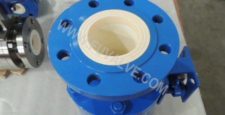
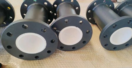
Lime / gypsum slurry transportation
The abrasion of slurry is mainly due to the impact and damage of solid particles (especially silicate) in the slurry on the abraded materials. Flue gas desulfurization slurry media mainly consists of limestone (CaCO3) Partikel (containing a small amount of SiO2) or gypsum (CaSO4-2H2O) particles and water. At higher flow rates, these particles can cause severe abrasion or erosion to the inner wall of the pipe.
Zur selben Zeit, the slurry is weakly acidic, and also mixed with some chloride ions, usw., these substances will have a chemical reaction with the metal pipe wall and make the steel pipe corrosion, until rotten through, affecting the service life of the desulfurization device.
Cl- easier than oxygen adsorption on the metal surface, and the oxygen crowded out, so that the passivation of the metal state has been partially destroyed and the occurrence of pore corrosion, some stainless steel materials are also difficult to avoid. Slurry corrosion of metal pipes in the form of: pitting, crevice corrosion, stress corrosion, fatigue corrosion, galvanic corrosion and so on.
Und dazu, the slurry pipe for two-phase flow. Two phase flow is characterized by the flow rate must be controlled within the appropriate range. High flow rate is prone to wear and tear and greatly increase the resistance of the pipeline, while the flow rate is low will produce deposits, narrowing the circulation surface of the pipeline, until blocked.

-400x231.jpg)